1 How to Reassemble Doosan DX520LC and DX480LC Hydraulic Excavator Stroke Motor Speed Reducer
Doosan Diagnostic Tool UVIM Support Doosan Excavators High Quality
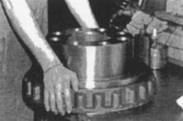
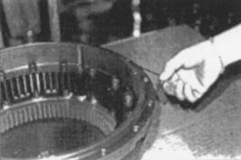
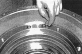
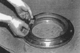
2 Installsealto jig. Figure 92.
3 Installjigto housing. Figure 93.
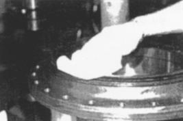
4 Cleanseal surface. Figure 94.
2020 Doosan Daewoo Excavator Operation and Repair Manual PDF
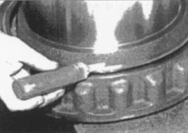
5 Installsealto hub using jig used in Step 1. Figure 95.
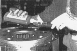
6 Applylubricant to seal surface. Figure 96.
- Supportball bearing housing with spacers (1 and 2, Figure 97) and install bearing into housing. Install spacer between balls,noting diameter shown in illustration.

2022.11 Doosan DMS-5 3.0.5 Data Monitoring System Diagnostic Software
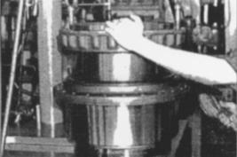
8 Installupperballs and upper housing. Figure 98.

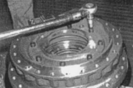
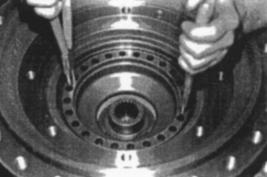
09 Itall hub to housing. Figure 99.
10 Presshubinto housing using a press and a stopper. Figure 100.

Doosan Diagnostic Tool DDT G2 SCAN( ECU ,DCU)Software 2016
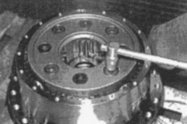
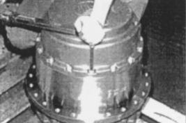
11 Installfourbushings using a press. Figure 101.
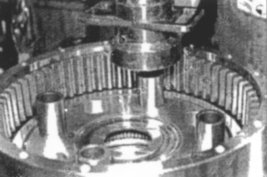
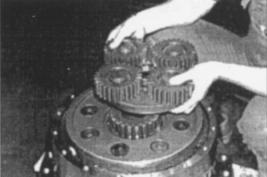
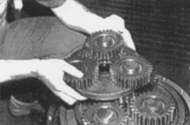
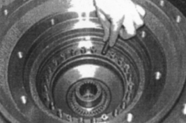
12 Assembleplanetary gear assembly. Figure 102.
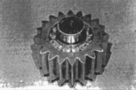
13 Installfour planetary gear assemblies, using press. Figure 103.
14 Tightengear box of planetary gear assembly to 150 Nm (110.7 ft lb). Figure 104.
15 Assemblethird shift sun gear. Figure 105.
16 Assemblethe second shift reduction assembly. Figure 106.
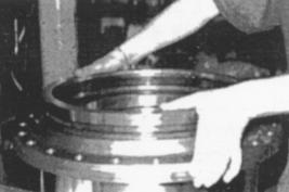
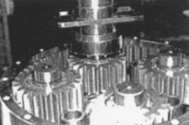
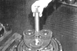
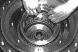
17 Placeplanetary gear carrier on hub. Figure 107.
18 Pressplanetarygear carrier into hub. Figure 108.
Doosan Diagnostic Tool UVIM Support Doosan Excavators High Quality
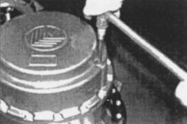
19 Apply loctite to planetary gear carrier fastening bolts. 19. Install and tighten bolts. Figure 109.
NOTE: In next step, the O–ring and backup rings are
different. Be careful not to switch them.
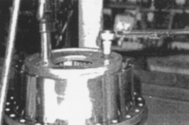
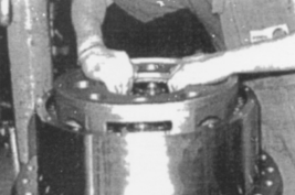
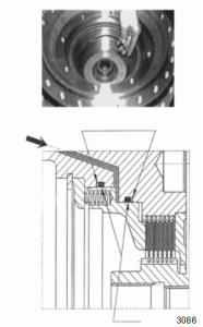
20 InstallO-ringto end cover. Figure 110.
21 Installend cover to housing.
NOTE: Apply Loctite 243 to bolts and torque to 10 Nm
(7.38 ft lb). Figure 111
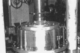
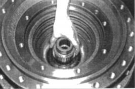
22 Tighten plugs to 6 – 8 Nm (4.42 – 5.90 ft lb). Figure 112.
23 Turnhousingover and install second shift sun gear. Figure 113.
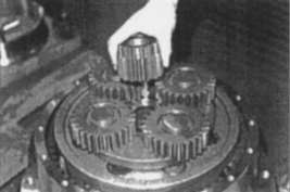
24 Installfirstshift planetary gear assembly. Figure 114.
25 Install first shift sun gear. Figure 115
26 InstallO-ring(1, Figure 116) and backup ring (2) into hub groove.
NOTE: The O–ring and backup rings are different. Be
careful not to switch them.
Doosan Diagnostic Tool UVIM Support Doosan Excavators High Quality
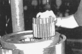
27 Install brake shaft while turning the reduction gear assembly. Figure 117
 .
.
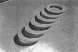
28 Installbrake disc assembly, starting with a copper disc (seven pieces) and alternating with steel discs (six pieces). Figure 118 and Figure 119.
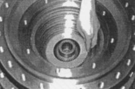
Installjigto hub and insert spring retainer disc under left side of retaining ring. Figure 120.
Heavy Duty Truck Diagnostic Tool
29 Installretainingring using retaining ring pliers. Figure 121.
30 InstallO-ringto hub groove. Figure 122.
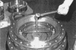
31 Placebrakepiston inside hub being careful not to damage seal. Figure 123.
32 Insertspringsinto brake piston holes. Figure 124.
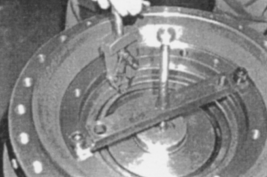
33 Installretainerdisc. Figure 125.
34 InstallO-ringto motor flange groove. Figure 126.
35 Tightenmotor flange to hub. Figure 127.