This article mainly introduces removaland and installtion Isuzu 4JH1 Engine
ISUZU US-IDSS Diagnostic Service Truck Diagnostic System 06.2021
Removal CAUTION:
Precautions when instaling or removing the engine· Always apply chock blocks to the vehicle wheels.
· Select an engine hoist that is able to withstand the weight of the engine.
· Do not get under the engine while it is hoisted.
· Never put your hands where they can get easily caught.
1. Disconnect the battery cable negative terminal.
2. Drain the engine coolant.
3. Remove the cab.(Non-tilt cab model only)
Refer to “FRAME AND CAB”Section 2.
4. Disconnect the B terminal from the starter motor.
5. Disconnect the engine ground cable from the frame.
6. Remove the front exhaust pipe and exhaust brake.
Refer to “Exhaust Pipe”and “Exhaust Brake”in Section 6F, Engine Exhaust.7. Remove the transmission.
Refer to “Manual Transmission”in Section 7B.
8. Disconnect the heater hose.
9.Remove the air duct and PCV hose.
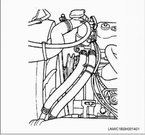
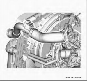
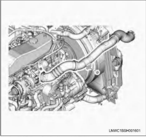
10.Remove the air intake pipe and hoses.
·Remove the pipe the bracket.
. Remove the hose from the intercooler with the pipe attached.
Remove the hose from the turbocharger with the pipe attached.
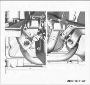
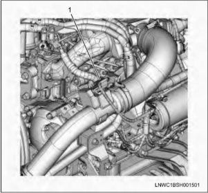
11 Disconnect the boost sensor connector.(Euro4 specification)
Legend
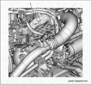
.Boost sensor connector
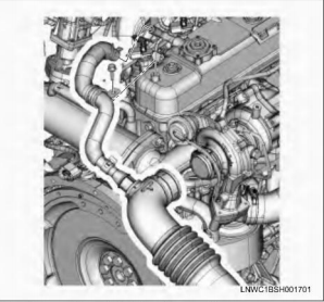
12.Remove the air intake pipe and hoses.
·Remove the pipe from the bracket.
·Remove the hose from the intercooler with the pipe attached.
·Remove the hose from the intake throttle valve with the pipe attached.
13.Disconnect the fuel hose.
·Disconnect the fuel inlet hose and fuel return hose from fuel supply pump.
14.Disconnect the ECM connector and clip.
15.Disconnect the vacuum hose from the vacuum pump.
16.Remove the radiator.
Refer to “Radiator”in Section 6B Engine Cooling.
17.Remove the power steering pump and bracket assembly.
a.Loosen the idler pulley lock nut.
b.Loosen the adjust bolt then remove the drive belt.
c.Remove the pipe bracket fixing bolt and clip.
d.Remove the power steering pump fixing bolts pump to chassis frame side use the wire.
18.Remove the support rubber.
a.Right hand.
·Remove two fixing nuts at the cross member side.
b.Left hand
·Remove two fixing nuts at the cross member side.
19. Remove the engine assembly.
a. Lift engine carefuly by using hoist.
b. Lift front part of engine higher than rear part of it.
c. Take out engine assembly taking care not to damage full pipes, brake pipes and so on.
Installation
1. Install the engine assembly to the vehicle.
· Position engine mountings by using hoist.
2. Install the support rubber.
· After all fixing boltls(left: two bolts, right: two bolts)
were inserted to every holes, and engine assembly and tighten fixing bolts to the specified torque Tightening torque:48 N.m(4.9 kgm/35 lbft)
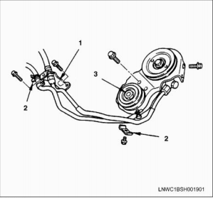
3.Install the power steering pump and bracket assembly.
. Install the power steering pump and pipe bracket then tighten bolts to the specified torque.
Tghtening torque Pump bolts:19 N-m(1.9kg-m/14 lb-t) Pipe bracket bolts:19 N-m(1.9kg-m/14 lb-ft)
Clip bolt:10N-m(1.0kg-m/87 lb-in)
Legend
1.Bracket
2.Clip
3.Lock nut
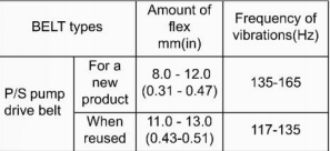
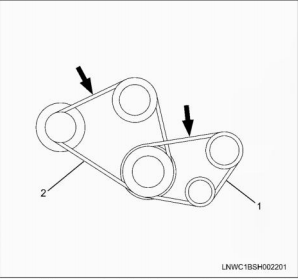
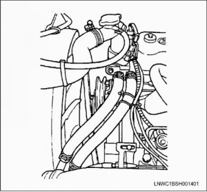
· Install the power steering pump drive belt(1)
and adjust belt tension.
Check drive belts for wear or damage, and replace with new ones as necessary.
Check belts for tension, and adjust as necessary.
· Push the middle of belts with a force of 98 N(10
kg) and check each bolt for deflection.
Standard deflection
·P/S pump lock bolt loose, adjust belt tension with adjust belt. Tightening torque Idler lock nut27 N-m(2.8 kgm/20 lbft)
4. Install the radiator.
Refer to “Radiator”in Section 6B Engine Cooling.
5. Connect the vacuum hose from the vacuum pump.
6. Connect the ECM connector and clip.
7. Connect the fuel hose.
· Connect the fuel inlet hose and fuel return hose to fuel supply pump.
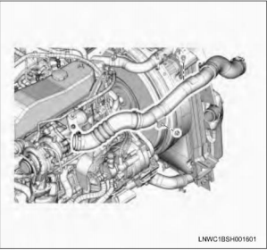
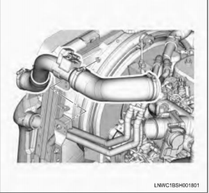
8. Install the air intake pipe and hoses.
. Install the pipe and hoses between the intake throttle valve and intercooler.
· Use a new hose clamp, align it with the marking, and tighten it at the specified torque.
Tightening torque Clamp:8.0N-m(0.8kg-m/71 lbin)
· Fix the air intake pipe to the bracket.
Tightening torque:20 Nm(2.0 kg-m/177.5 lb-in)
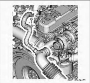
9. Connect the boost sensor connector.(Euro4specification)
Legend
1. Boost sensor connector
10. Install the air intake pipe and hoses.
· Install the pipe and hoses between the turbocharger and intercooler.
· Use a new hose clamp, align it with the marking, and tighten it at the specified torque.
Tightening torque Clamp:8.0N-m(0.8kg-m/71lbin)
· Fix the air intake pipe to the bracket.
Tightening torque:20 N-m(2.0kg-m/177.5 lbin)
11. Install the air duct and PCV hose.
Tightening torque Air cleaner side: Clamp:6.4N-m(0.65kg-m/56.4lb-in)
Turbocharger side:
8.0Nm(0.8kg-m/71 lb-in)
12.Connect the heater hose.
13. Install the transmission.
Refer to “Manual Transmission”in Section 7B.
14. Install the front exhaust pipe and exhaust brake.
Refer to “Exhaust Pipe”and”Exhaust Brake”in Section 6F, Engine Exhaust.
15. Connect the engine ground cable from the frame.
16. Connect the B terminal from the starter motor.
17. Install the cab.(Non-tit cab model only)
Refer to “FRAME AND CAB”Section 2.
18. Refill the engine coolant.
19. Connect the battery cable negative terminal.